Validating Wi-Fi 7 Multi-RU + OFDMA Schedulers Under Asymmetric Load
Wireless Testing
 Nimmy Varghese
August 10, 2026
Nimmy Varghese
August 10, 2026



 Nimmy Varghese
August 10, 2026
Nimmy Varghese
August 10, 2026
Wi-Fi validation testbeds are full of unexpected surprises. When verifying next-generation Wi-Fi 7 (802.11be) features on hardware, what you see on paper rarely matches what your sniffer shows you on the first try.
This article examines one of the most significant advances Wi-Fi 7 brings to spectrum management: Wi-Fi 7 Multi-RU OFDMA scheduling. Rather than relying on theoretical benchmarks, we put a Wi-Fi 7 access point through a deliberately asymmetric, high-contention traffic scenario and used over-the-air packet analysis to verify whether the scheduler behaved as expected under this workload. The captures show observable, measurable Multi-RU allocation behavior at the frame level.
Definition
Orthogonal Frequency Division Multiple Access (OFDMA) is a multi-user version of the OFDM transmission technique that has been the foundation of Wi-Fi since 802.11a. Where traditional OFDM allocates the entire channel bandwidth to a single user for each transmission opportunity, OFDMA subdivides the channel into smaller frequency allocations called Resource Units (RUs), allowing an access point to serve multiple clients simultaneously within a single transmission window.
Wi-Fi 6 introduced OFDMA to the wireless LAN space for the first time. Wi-Fi 7 takes this further by introducing Multi-RU (MRU) allocation, which allows the scheduler to assign multiple non-contiguous or contiguous Resource Units to a single station within the same OFDMA transmission opportunity. This enables the access point to dynamically match spectrum allocation to traffic demand at a much finer granularity than was previously possible.
The practical effect is significant. An access point running a well-implemented Wi-Fi 7 scheduler can simultaneously give a small, latency-sensitive VoIP stream exactly the narrow slice of spectrum it needs, while handing a large TCP saturation client a much wider block of resources to maximise its throughput. Both clients are served in the same transmission window without interference or competition.
How Wi-Fi 7 handles competing traffic under congestion is explored in detail in our QoS scheduling analysis.
A Resource Unit (RU) in OFDMA terminology is a defined block of subcarriers within the channel. In a 160 MHz Wi-Fi 7 channel, the largest single RU spans 996 tones, which corresponds to roughly 80 MHz of spectrum. In standard OFDMA operation, each station receives one RU per transmission opportunity.
Multi-RU allocation breaks this one-to-one constraint. Under Multi-RU, the scheduler can assign multiple RUs to a single station within the same transmission, effectively aggregating spectrum blocks to match the station’s demand. A 2×996-tone Multi-RU allocation, for example, combines two 80 MHz blocks into a single 160 MHz allocation for one station, maximizing that client’s available bandwidth while the scheduler reserves separate resource slots for other clients.
This capability is particularly valuable in asymmetric traffic environments, where some clients need high bandwidth and others need low latency. Multi-RU gives the scheduler the flexibility to satisfy both requirements simultaneously rather than forcing a compromise between them. This is also one of the key scenarios that 802.11be OFDMA scheduler testing is designed to verify, confirming that the feature is not just present in the firmware but actively functioning under real traffic conditions.
To push a Wi-Fi 7 access point’s scheduler to its limits, an asymmetric, multi-user, mixed-traffic scenario was designed as part of a structured Wi-Fi 7 test bed setup. Two distinct client stations with opposing Quality of Service (QoS) requirements were introduced to determine whether the AP could efficiently slice the channel:
| Component | Traffic Profile |
|---|---|
| STA1 | A Windows client equipped with an Intel Wi-Fi 7 BE201 chip, tasked with generating small, continuous VoIP-style UDP streams alongside diagnostic pings to measure path jitter under load. |
| STA2 | A Linux client with Intel Wi-Fi 7 BE201 chip, generating massive downstream TCP saturation across 8 parallel iPerf3 streams, is used to generate heavy channel load. |
| APUT Channel, Channel Width | 160 MHz, Channel 36 |
| Sniffer Device | To capture and dissect what happens over the air at the microsecond level, the testbed utilizes a dedicated, non-participating capture node running Wireshark v4.2.2 combined with an Intel Wi-Fi 7 BE201 PCIe adapter configured in Monitor Mode |
| Environment | RF Chamber |
| Traffic Generation Tool | iPerf3.21 (CLI), Ping (CLI) |
The goal was straightforward: determine whether this AP, in this RF chamber setup, could satisfy conflicting traffic demands while efficiently allocating spectrum resources across two associated Wi-Fi 7 clients.
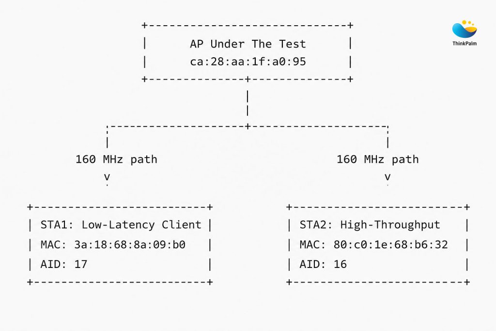
Fig 1a: Multi-RU Validation Test Topology
For a closer look at what modern wireless test labs look like today and how they differ from legacy approaches.
Before any Multi-RU Validation analysis can be trusted, the relationship between a station’s physical MAC address and its assigned Association ID (AID) must be established. When an AP coordinates an OFDMA channel, it does not address devices by their 48-bit MAC addresses inside the control frame body. Instead, it uses a 12-bit AID assigned during network entry. Every scheduler decision traced in the subsequent phases depends on this mapping being verified first.
Association responses were analyzed to identify and confirm the AID assigned to each station:
| Station | AID |
|---|---|
| STA1 | 17 |
| STA2 | 16 |
The AID is the scheduler’s primary addressing mechanism inside OFDMA trigger frames. Without confirmed AID-to-MAC mappings, it is impossible to determine which station the AP is allocating resources to in any given trigger frame. Establishing this mapping through actual association frame captures, rather than assuming it from configuration, ensures that every subsequent scheduler observation is grounded in verified over-the-air evidence rather than expected behavior.
STA1 Mapping — VoIP Client
In Frame 1653, the AP successfully processes the connection handshake for the low-latency client.
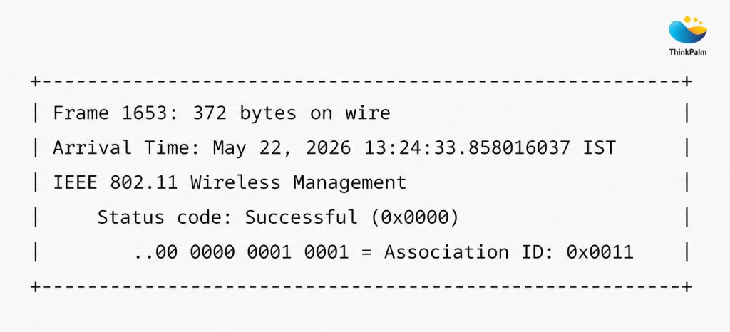
Fig 1b: STA1 Association Response
Result: STA1 (3a:18:68:8a:09:b0) is formally registered to AID 17.
STA2 Mapping — TCP Congestion Client
Shortly after, Frame 592 captures the network entry for the high-capacity saturation client.
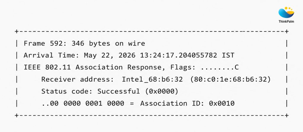
Fig 1c: STA2 Association Response
Result: STA2 (80:c0:1e:68:b6:32) is formally registered to AID 16.
This mapping later allowed every scheduler decision in the subsequent phases to be traced back to a specific device with confidence.
With both stations associated and traffic streaming, the channel becomes heavily congested. The sniffer tracked tight inter-frame arrival intervals as the parallel TCP streams flooded the medium:
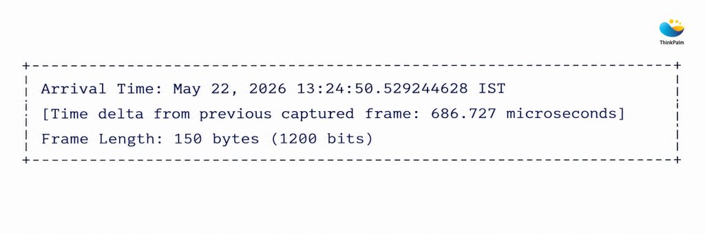
Fig 1d: The Frame 2718 Timestamp
To prevent data collisions between the 8 TCP streams and the VoIP pings, the AP’s scheduler takes control of the medium. By applying the display filter wlan.fc.type_subtype == 0x0012, Frame 2718 was successfully isolated, a multi-user control packet orchestrating medium access.
This is a core step in 802.11be OFDMA scheduler testing, where isolating trigger frame types is the primary method for confirming that the scheduler is actively coordinating multi-user transmissions rather than relying on standard contention-based access.
The captured trigger frame confirms three critical aspects of the scheduler’s operation:
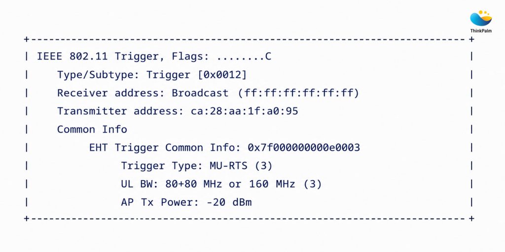
Fig 1e: MU-RTS Trigger Frame Captured Over-the-Air
These trigger frames confirmed:
The wireless medium was no longer operating through contention alone; the AP had assumed active scheduling control.
Understanding how EMLSR shapes multi-link connection behavior provides useful context for how Wi-Fi 7 coordinates radio resources.
The definitive proof of Wi-Fi 7 Multi-RU scheduling emerged from the EHT User Information fields within Frame 2718. Expanding the User Info container of the same trigger frame yields the critical evidence:
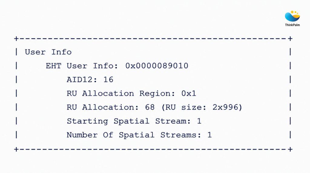
Fig 1f: Multi-RU Allocation Evidence
The EHT User Info block explicitly addresses AID12: 16. Based on the AID mapping confirmed in Phase 1, this is STA2, the high-capacity TCP saturation client.
The RU Allocation field decodes an aggregate RU size of 2×996. A single 996-tone RU represents a full 80 MHz channel block. By allocating 2×996, the scheduler is dynamically pairing two maximum-sized 80 MHz spectrum slabs together for a single station, covering the full 160 MHz channel width in one allocation.
By using MU-RTS to reserve dedicated 160 MHz uplink capacity for STA2’s ACK traffic ahead of time, the AP keeps that traffic protected from contention, keeping the TCP window open and throughput high. Simultaneously, the AP holds independent, protected resource slots open for STA1 (AID 17), allowing the VoIP stream to maintain 0% packet loss under complete environmental saturation.
This is Multi-RU allocation working exactly as the IEEE 802.11be standard intends. The scheduler is not making a compromise between two competing clients. It is satisfying both simultaneously by giving each precisely the resources its traffic profile requires.
In our earlier MLO connection performance benchmark, we measured how vendor firmware decisions shaped pre-association behavior across three access points.
For this validation, a pass required three observable conditions: confirmed AID-to-station mapping from association responses, captured AP-controlled trigger frames during the mixed-traffic run, and decoded RU Allocation values showing Multi-RU assignment to the intended high-throughput station while the latency-sensitive stream remained loss-free:
| Architectural Check | Target Metric | Over-the-Air Sniffer Evidence | Verification Status |
|---|---|---|---|
| OFDMA Triggering | Control Type 0x0012 | Active MU-RTS frames captured on Ch. 36 | PASS |
| STA1 Network Entry | Unique Mapping | Handshake assigns Unicast Link to AID 17 | PASS |
| STA2 Network Entry | Unique Mapping | Handshake assigns Unicast Link to AID 16 | PASS |
| Wi-Fi 7 Multi-RU | Aggregated Tones | AID12: 16 explicitly allocated 2×996 | PASS |
| QoS Prioritization | Stream Isolation | VoIP traffic records 0% packet drop rate | PASS |
Every architectural check passed with direct sniffer evidence for this test case. The results confirm that the access point demonstrated Multi-RU OFDMA scheduling under asymmetric traffic conditions in the measured setup, rather than only advertising the feature in configuration or datasheet material.
ThinkPalm is a Wi-Fi pre-compliance testing service provider with dedicated wireless engineering test lab infrastructure and deep expertise in 802.11be pre-certification testing and protocol validation. Our RF engineering services for OEMs and chipset manufacturers include over-the-air validation for chipset qualification, Wi-Fi 7 RF validation testing, and pre-compliance assessments across 802.11be, Wi-Fi 6E, and legacy standards.
Learn More About Our Wi-Fi 7 Testing CapabilitiesThe validation results confirm that this Wi-Fi 7 access point successfully implements advanced Wi-Fi 7 Multi-RU OFDMA scheduling under asymmetric multi-user traffic conditions. Over-the-air packet analysis verified MU-RTS trigger-based OFDMA coordination, accurate AID mapping for both connected stations, and dynamic allocation of 2×996-tone Resource Units to the high-throughput client.
Equally important, the access point maintained stable low-latency VoIP traffic with 0% packet loss while simultaneously handling heavy TCP saturation traffic. This confirms that the scheduler can balance competing traffic demands without compromising application quality for either client.
Through over-the-air packet analysis and client identity mapping, this study confirms that the Wi-Fi 7 scheduler efficiently utilizes available spectrum resources while supporting both bandwidth-intensive and latency-sensitive workloads simultaneously. For network architects and wireless engineers evaluating Wi-Fi 7 hardware, this kind of Wi-Fi 7 RF validation testing provides confidence that the access point’s advanced scheduling capabilities are not just advertised features. They are functional, measurable, and deployment-ready. Studies like this are part of how ThinkPalm continues to bridge the gap between wireless standards and real-world network deployments.
Nimmy Varghese is a Wi-Fi Test Engineer focused on Wi-Fi standards validation and certification testing. Her work involves validating wireless features, interoperability, protocol compliance, end-to-end connectivity, and optimizing test workflows for next-generation Wi-Fi devices.