 Asbin Immanuel
November 20, 2026
EVPN-VXLAN is a standards-based data center networking technology that pairs two protocols: VXLAN as the data plane and BGP EVPN as the control plane. Together they let engineers build scalable, multi-tenant fabrics without stretching VLANs across the network or depending on Spanning Tree Protocol (STP).
VXLAN (Virtual Extensible LAN, an IP tunnel) is the data plane. It carries Layer 2 Ethernet frames across a Layer 3 IP network. So, the Layer 2 frame is encapsulated inside a Layer 3 packet, that is, inside IP tunnel headers. The data plane technology defines how the bridges located in different sites are virtually connected.
In a Clos architecture, the spine device forwards the frames based on the IP tunnel headers and is unaware of the underlying Layer 2 frame. In the leaf device, the tunnel header identifies the bridge domain and the traffic gets forwarded based on the inner Layer 2 header within that bridge domain.
BGP EVPN (Ethernet VPN) is the control plane. It distributes MAC and IP reachability between switches, so they no longer need to flood traffic to find out where hosts live.
Put simply, if you are asking “what is EVPN VXLAN?”, the answer is that VXLAN builds the tunnels, and EVPN tells the tunnel endpoints what is reachable through each one.
This guide explains how EVPN VXLAN works from the ground up. The EVPN-VXLAN architecture, examines the VXLAN header and VXLAN packet format, explores remote MAC address learning and BGP EVPN route types, and walks through real FRRouting (FRR) packet outputs.
VXLAN is designed for large-scale data center network virtualization. It overcomes the physical boundaries and scale limits of traditional Layer 2 VLANs, STP bottlenecks, and the 4,094 VLAN ID ceiling. EVPN adds the control plane that makes the overlay efficient, resilient, and easy to operate.
According to RFC 8365, the following encapsulation types are defined as “BGP Tunnel Encapsulation Attribute Tunnel Types” in IANA:
| Value | Name |
|---|---|
| 8 | VXLAN Encapsulation |
| 9 | NVGRE Encapsulation |
| 10 | MPLS Encapsulation |
| 11 | MPLS in GRE Encapsulation |
| 12 | VXLAN GPE Encapsulation |
The FRR protocol stack currently supports only VXLAN encapsulation. At ThinkPalm, we have the expertise to enhance the support for the other encapsulation types defined in the standard as well.
Traditional Layer 2 designs hit the same problems repeatedly: VLAN IDs run out, STP blocks redundant links, and flood-and-learn sends broadcast, unknown unicast and multicast (BUM) traffic everywhere. EVPN VXLAN solves these directly:
An EVPN VXLAN architecture has three cooperating layers:
A routed spine-leaf IP network. Its only job is to give each VXLAN Tunnel Endpoint (VTEP) a stable, reachable address.
VXLAN tunnels between VTEPs. A VTEP, usually a leaf switch, wraps traffic from local hosts and unwraps traffic from remote VTEPs.
BGP EVPN, which shares MAC, IP and VNI information between VTEPs.
This layered model is a core building block of modern software-defined networking, where the network is controlled through software instead of box-by-box configuration.
Think of VXLAN as a “virtual cable” connecting two separate switches over a standard IP network. It encapsulates Layer 2 Ethernet frames into UDP/IP packets, so workloads on different physical networks behave as if they share one local network. Virtual Network Identifiers (VNIs) segment traffic much like VLAN IDs do in classic bridge domains.
| Feature | VLAN | VXLAN |
|---|---|---|
| Segment ID | 12-bit VLAN ID (4,094 usable) | 24-bit VNI (over 16 million) |
| Transport | Layer 2 Ethernet, trunked between switches | Encapsulated in UDP/IP over a Layer 3 network |
| Loop prevention | Spanning Tree Protocol | Routed underlay with ECMP, no STP across the fabric |
| Reach | A single Layer 2 domain | Across racks, buildings and sites |
| Multi-tenancy | Limited by the VLAN ID space | VNI plus VRF per tenant |
| Standard | IEEE 802.1Q | RFC 7348 (data plane), RFC 8365 (EVPN) |
Read how ThinkPalm supported a leading data communication company with advanced cellular backhaul equipment development.
Read Case Study →When an Ethernet frame is encapsulated by a VTEP, several headers are prepended to the original payload. This is the VXLAN packet format, and understanding it is the key to reading captures and troubleshooting MTU problems.
Below is an ASCII representation of a captured Wireshark frame breakdown for a sample VXLAN packet:
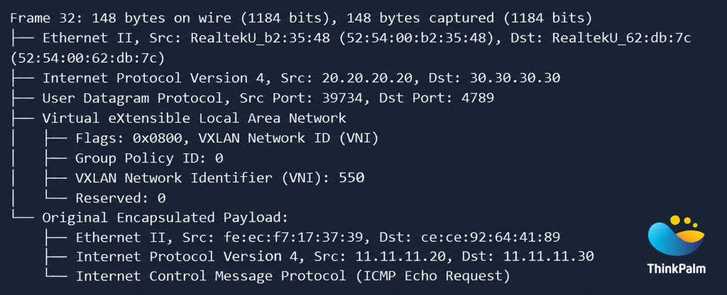
VXLAN packet capture showing outer headers, VNI 550, and the encapsulated ICMP request.
On local switches, a 1:1 mapping typically exists where local VLANs are mapped directly to a specific VNI. The VNI serves as the global network identifier across the Layer 3 fabric, allowing different switches to map their own local VLAN tags into a unified global overlay domain.
MAC learning in VXLAN networks is categorized into two distinct operational models: Local MAC Learning and Remote MAC Learning.
Local MAC learning occurs when a device (switch or VTEP) learns the source MAC address of a frame received directly on one of its physical ports or logical local interfaces (e.g., VLAN trunk or access port).
Remote MAC learning refers to a switch or VTEP learning MAC addresses located behind remote VTEPs across the L3 network fabric. Irrespective of how the tunnel is established, local MAC learning remains identical. However, remote MAC learning varies depending on the setup method:
When remote VTEPs are statically configured without a control plane, remote MAC learning relies on a data-plane dynamic flood-and-learn mechanism over the VXLAN tunnel. Broadcast, Unknown Unicast, and Multicast (BUM) traffic must be replicated to all VTEPs.
In modern enterprise networks, BGP EVPN is utilized as the control plane. MAC and IP addresses are advertised using BGP Network Layer Reachability Information (NLRI) messages. Remote VTEPs receive these advertisements and proactively populate their local MAC/forwarding tables without needing data-plane flooding.
EVPN follows three key steps. First, each VTEP learns local hosts the normal way. Second, it advertises what it learned to its BGP peers as EVPN routes that carry the MAC, the IP, the VNI and its own VTEP address as the next hop. Third, receiving VTEPs import these routes and program their tables, directing unicast traffic through the correct tunnel. By moving MAC learning into the control plane, EVPN also supports other data plane encapsulations, although data centres most commonly use VXLAN.
BGP EVPN defines several route types to distribute reachability information. RFC 7432 defines types 1 to 4, and the IP prefix route (type 5) comes from RFC 9136. RFC 8365 describes how these routes are used with VXLAN and other network virtualization overlays. The table summarizes all five BGP EVPN route types.
| Type | Name | Purpose | Defined in |
|---|---|---|---|
| 1 | Ethernet Auto-Discovery | Multihoming support, fast convergence and aliasing, advertised per ESI and per EVI | RFC 7432 |
| 2 | MAC/IP Advertisement | Host MAC (and optionally IP) reachability, ARP suppression and MAC mobility | RFC 7432 |
| 3 | Inclusive Multicast Ethernet Tag | Automatic VTEP discovery and the BUM flood list (head-end replication) | RFC 7432 |
| 4 | Ethernet Segment | Discovery of VTEPs on the same Ethernet segment and designated forwarder election | RFC 7432 |
| 5 | IP Prefix | Inter-subnet routing and advertising external or summarized prefixes | RFC 9136 |
For basic Layer 2 and Layer 3 overlay operation, the two most important routes are Type 2 and Type 3.
According to RFC 7432, a Type 2 route is originated and sent to remote peers whenever a MAC address (and optionally its associated IP address) is learned locally. The remote peer installs this entry into its local MAC and IP forwarding tables for direct unicast traffic forwarding.
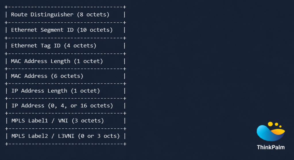
EVPN Type 2 route format showing MAC/IP advertisement fields, address lengths, and VNI information.
Type 3 routes are generated by VTEPs to auto-discover other peer VTEPs attached to the same VNI segment. They are specifically used to construct the Head-End Replication (HER) list for flooding Broadcast, Unknown Unicast, and Multicast (BUM) traffic across the L3 underlay.
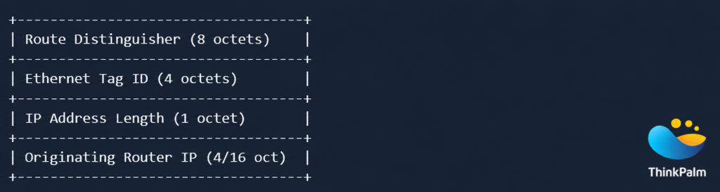
EVPN Type 3 (IMET) route format showing the route distinguisher, Ethernet Tag ID, and originating router IP address.
Type 1 and Type 4 routes support multihoming. A server connected to two leaves shares an Ethernet Segment Identifier (ESI), and these routes allow fast failover, load balancing across both leaves and designated forwarder election for BUM traffic. Type 5 routes carry IP prefixes, so they are how a fabric advertises subnets, default routes or external prefixes into a tenant VRF for inter-subnet routing.
Each EVPN route includes a Route Distinguisher (RD), which makes it unique in the BGP table, even when two VTEPs advertise the same MAC address in different segments. A Route Target (RT) is an extended community that controls import and export: a VTEP only installs routes whose RT matches one of its configured import targets. Together they keep tenants separated inside a shared BGP table.
To illustrate EVPN-VXLAN operation, consider a standard 3-node topology consisting of two Provider Edge switches (PE1, PE2) and a core Provider router (P):
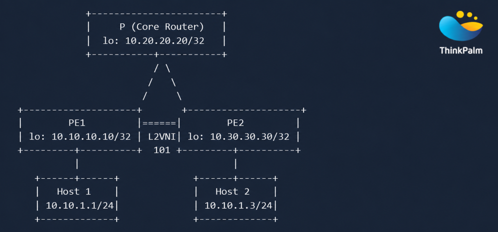
EVPN-VXLAN topology showing PE devices, core routing, and host connectivity.
Host 1 sends an ARP request asking for the MAC address of Host 2. Based on the source MAC of the ARP request:
Local MAC learning in PE1 from the H1 ARP request, add entry [H1 source MAC –> local port] and trigger BGP EVPN Type 2 route to PE2
Remote MAC learning in PE2 from the BGP EVPN Type 2 originated by PE1 and entry [H1 source MAC –> tunnel towards PE1] gets added
When the destination MAC is a broadcast or is not found, the frame is flooded according to the HER list.
When the destination MAC is found, the packet is forwarded toward the host or the core router.
Below are exact command outputs captured from FRRouting (FRR) on PE1 demonstrating VNI bindings, MAC table states, and EVPN route exchanges.
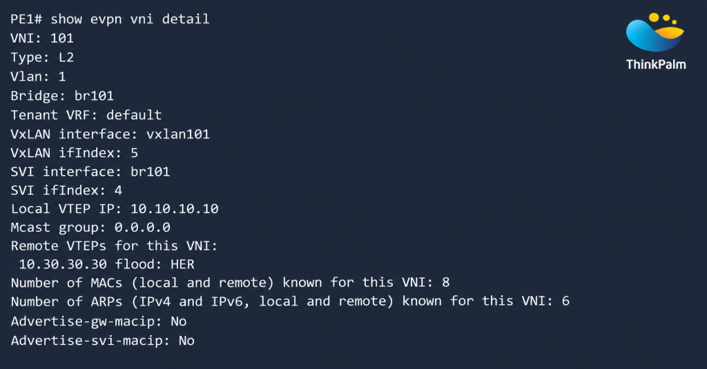
EVPN VNI 101 configuration details showing VXLAN interfaces, local and remote VTEPs, and MAC/ARP information.
Analysis: The output confirms VNI 101 is configured as Layer 2, bound to native VLAN 1 on bridge br101. The remote VTEP 10.30.30.30 (PE2) is discovered and designated for Head-End Replication (HER).
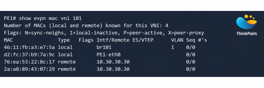
EVPN MAC table for VNI 101 showing local and remote MAC addresses, associated interfaces, and remote VTEP information.
Analysis: PE1 tags local MACs (SVI br101 and Host-1 on PE1-eth0) as ‘local’ in its MAC table for VNI 101. It identifies MACs learned from PE2 (SVI and Host-2) as ‘remote’ and associates them with VTEP 10.30.30.30.
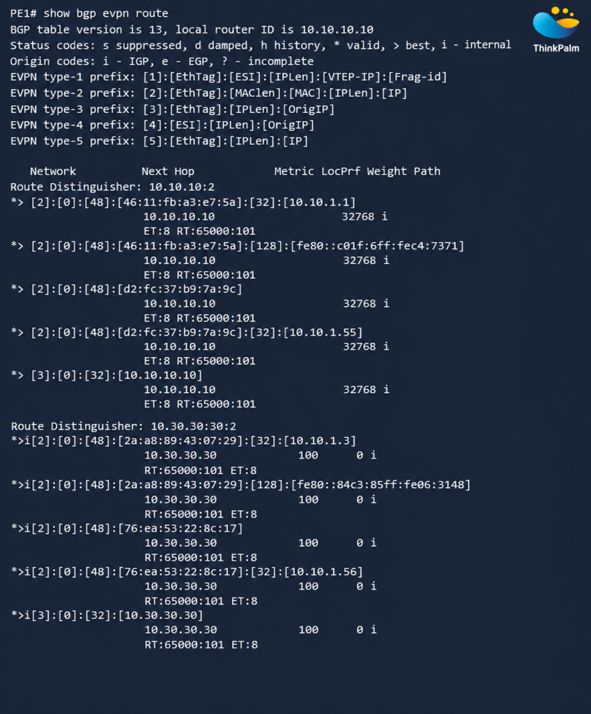
PE1 originates the first 5 entries under RD 10.10.10.10:2 in the EVPN route table above, while peer PE2 sends the remaining 5 entries under RD 10.30.30.30:2.
Checking control plane and data plane state like this is also the basis of Layer 2 and Layer 3 protocol testing. To see how teams are modernizing that process, read about autonomous network testing and validation.
To summarize how EVPN VXLAN operates, it is important to understand the difference between Layer 2 VNIs and Layer 3 VNIs:
Connects remote Ethernet bridge instances across an IP network tunnel. It is represented as the tuple {L2 VNI, Destination VTEP IP, MAC Address} and is derived directly from EVPN Type 2 advertisements.
Connects separate VRF routing tables across an IP tunnel for inter-subnet routing. It is represented as the tuple {L3 VNI, Destination VTEP IP, IP Address} and is populated using EVPN Type 5 (IP Prefix) and Type 2 (MAC/IP) advertisements.
EVPN VXLAN is now a common way to build scalable data center networks. VXLAN provides the tunnels and the large VNI space, and BGP EVPN provides the control plane that replaces flooding with MAC and IP advertisements. With the packet format, the Type 2 and Type 3 routes and the L2 and L3 VNI concepts in hand, the FRR outputs above become much easier to read.
Building, Integrating or Testing EVPN-VXLAN Fabrics?
ThinkPalm’s networking and communication services cover SDN/NFV, SD-WAN and network protocol development, supported by a dedicated testing lab.
Asbin Immanuel is a dynamic software development professional with around 12 years of extensive experience specializing in networking products, control and data plane architectures, and protocol stacks. Throughout his career—including key roles at ThinkPalm, Cisco, Capgemini Engineering and CARC—he has built deep expertise in FRR protocols stack, virtualization, and modern network automation tools. Passionate about continuous learning and innovation, actively explores emerging domains like quantum computing, AI/ML and advanced networking frameworks like SONIC.
One message is all it takes to get started. Tell us what you need, and we’ll take it from there, no long forms, no waiting around.

