Software has begun to influence our day-to-day lives. Each day we are using some sort of software, like switching on TV, locking our cars, switching on our air conditioners, all using remote control. We are connecting devices to devices daily and I had not even thought about this connectivity until I started working on GE Predix. These activities fall in the category of IoT (Internet of Things) which is about human interaction with objects. With this technology, devices can alert users when certain events or situations occur.
GE Predix deals with IIoT (Industrial Internet of Things) which differs greatly from IoT. The focus is not on connecting small devices but rather on connecting industrial assets, such as jet engines, turbines and locomotives to the cloud and each other, in a meaningful way. Think about a situation where we are able to identify well in advance that an industrial asset is about to stop working due to certain issues and are able to take actions before it affects our business?
PREDIX is the world’s first Industrial Internet Platform which connects machines, intelligence and people.
Predix Architecture Overview
Predix is a platform with components that span from machine to the cloud to enable industrial use cases. The primary components are:
- Predix Machine: The software layer responsible for communicating with industrial assets and Predix Cloud.
- Predix Connectivity: Applicable in situations where direct internet connection is not available. The machine can talk to the cloud through a virtual network.
- Predix Cloud: A secure cloud infrastructure where data from different sensors and devices can be stored and/or processed.
- Predix Services: Predix provides industrial services that developers can use to build, test and run industrial internet applications.
Predix Machine
Predix Machine provides secure cloud connectivity to Industrial assets and manages them. Developers can develop their own Predix machine with the help of Predix Machine Software Development Kit (SDK). Predix Machine SDK can be added as a plugin in Eclipse IDE and Predix machine can be generated by selecting individual bundles or by selecting certain feature groups where all necessary bundles needed for that feature will be included automatically. The Predix machine SDK can be downloaded as a zip from https://artifactory.predix.io, for which a valid Predix user account is needed.
The downloaded SDK will create the following directory structure
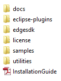
where
- docs: contains the SDK documentation.
- eclipse-plugins: used when the SDK is added to the eclipse as a plugin.
- edgesdk: contains SDK in various languages which helps write applications to communicate with devices through Data Bus.
- license: Holds license information.
- samples: contains sample applications which help in understanding the various Predix machine facilities.
- utilities: contains utility scripts that helps in generating Predix machine containers without installing SDK as a plugin in Eclipse.
- InstallationGuide: Predix Machine SDK installation guide.
The Predix Machine can be created and exported as a folder from Eclipse with the help of installation guide. The Predix Machine will have the following directory structure:
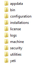
where
- appdata: can be used by all services as free space for reading and writing files.
- bin: holds the script to start and stop Predix machine.
- configuration: holds various configuration files needed for bundles in Predix machine.
- Installations: Yeti process monitors this folder for software to install.
- license: holds license details.
- logs: holds the runtime logs
- machine: this is the container directory with the following subdirectories:
- bin/predix – holds scripts for starting and stopping containers
- bin/vms – holds ini files which is an informal standard for configuration files
- bundles – holds a set of bundles (jar files). If any custom bundle needs to be created for running in Predix machine, it should be added to this folder.
- install – install scripts
- lib – holds runtime libraries (if any bundles require third-party libraries to be used, it can be added here)
- security: security policies and keystores.
- utilities: contains script for starting docker container.
- yeti: Yeti is a process that should be started when using provisioning bundles from Proximetry for installing new software. The zip to install is configured under Device Management and downloaded and placed in “installations” folder. This will be unzipped and Yeti will run any install.sh or install.bat inside the zip.
Machine Gateway Service
One of the main components of Predix Machine SDK is Machine Gateway Service which provides management of machine adapters in a centralized way. Its architecture is extensible so that developers can develop their own custom adapters for real time data streaming. Predix machine already has custom adapters for MQTT, Modbus, OPC-UA and health monitoring.
Let’s review how Predix machine sends data to cloud from sensors
To know how Predix machine sends data to cloud, an understanding of the below components is necessary.
- Data Node – Machine data is received in Data Nodes.
- Adapter – The Component that acquires data from sensors through different protocols like Modbus.
- Hoover Spillway – Specifies which machine adapter data subscriptions are to be released.
- Processor – If a customized logic needs to be injected or if the data needs to be aggregated or filtered, it can be done in processor.
- Store and Forward – Used to store data temporarily in FIFO order in case the destination is not reachable. The data is stored in an encrypted H2 file based database.
- River – Component to send data to a destination such as time series database in cloud or MQTT broker.
Let’s take an example – how Modbus data is send to cloud from sensors
Modbus is a serial communication protocol used for transmitting information over serial lines between electronic devices. It’s an open protocol which means manufactures can build it into their equipment without having to pay royalties. Modbus falls into two categories – ModbusTCP and ModbusRTU. The difference between the two is that ModbusTCP runs on an Ethernet physical layer and ModbusRTU is a serial level protocol. Modbus operates on memory registers to configure, monitor and control device I/O. Modbus has a simple structure that differentiates between four basic data types:
- Coil (Discrete Output) – 1 bit registers, may be read or written.
- Discrete Input – 1 bit registers used as inputs and may only be read.
- Input Register – 16 bit registers used for input and may only be read.
- Holding Register – Most universal 16 bit registers and may be read or written.
It’s up to the manufacturer to decide whether a particular device includes all these register types or not. Like most protocols, Modbus uses client/server type protocol. The client sends a request to server and server sends back response with requested data or acknowledgement. A Modbus message may also include a Unit ID, a number between 0 and 255 ,which is used to identify the server in networks.
Predix Machine is flexible enough, that the data can be sent by modifying configuration files only (no coding is required). For reading data from Modbus, there is already an adapter available in Predix – Modbus Adapter. This is added as a bundle in Predix Machine under machine/bundles folder. The configuration for Modbus Adapter can be found under configuration/machine. When Predix Machine starts, the bundle will be activated and started and it will read com.ge.dspmicro.machineadapter.modbus-0.config file. Given below is the content of a sample config file.
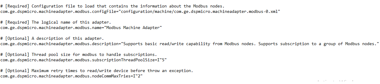
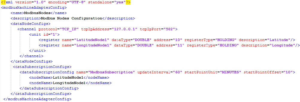
In the config file, we can specify the XML file to be read for Modbus configuration, a logical name and description for the Adapter, thread pool size to handle subscriptions and the maximum retries for connecting to a node if it fails while connecting. Given below is the content of com.ge.dspmicro.machineadapter.modbus-0.xml file. This configuration is used to read data from ModbusTCP.
The above XML file is the configuration to read data from two registers (with addresses 10 and 11) from a ModbusTCP running in localhost (127.0.0.1), 502 port. Each register is represented as a Data Node. The data in holding register address 10 is of data type double and it holds the latitude information. Likewise all data nodes that need to be read can be configured in the ‘dataNodeConfig’ section. The nodes that need to be subscribed can be given in ‘dataSubscriptionConfig’ section. In the above sample, the nodes given in ‘ModbusSubscription’ will start after 10 minutes from bundle start (startPointOffset is given as 10 minutes) and it will be read for every 1 minute (updateInterval is given as 60 seconds). This subscription needs to be specified in the spillway config file (configuration/machine/com.ge.dspmicro.hoover.spillway-0.config).
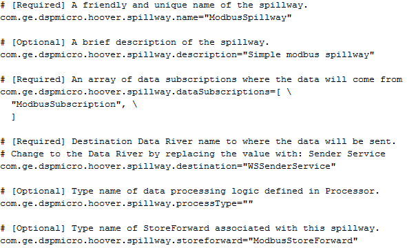
In the config file, we can specify a name for spillway, the data subscriptions to be considered, the name of destination river – where the data needs to be send and the name of the storeforward associated with this spillway. (We can also add a processor if we need to manipulate data in between and the processor can be specified in spillway config)
The storeforward name given in the spillway config needs to be specified in the storeforward config file (configuration/machine/ com.ge.dspmicro.storeforward-0.config).

The storeforward config files also hold information like username and password for H2 (used by Predix internally to temporarily store data) and more. This will be added by Predix internally without assistance. The spillway destination specified in spillway config needs to be specified in websocket river config (configuration/machine/com.ge.dspmicro.websocketriver.send-0.config).
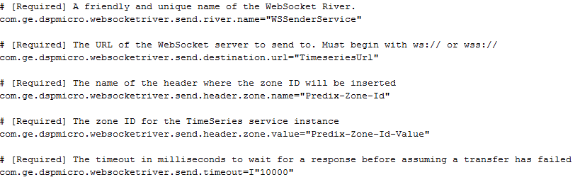
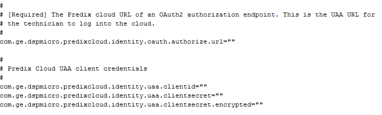
In the websocketriver config file, we should also specify the url of time series (Time series is a database that is optimized for handling time series data), Predix zone ID and its value (We will get these values from the free time series service provided by GE in the Predix cloud. An account needs to be created in https://predix.io/ and subscribed to the time series service). You should be authenticated in Predix Cloud and the username and password details need to be given in the identity config file (configuration/machine/ com.ge.dspmicro.predixcloud.identity.config). We will get the UAA (User Account and Authentication) url from Predix Cloud UAA service.
You can query the timeseries data using Time Series Query in Predix Tool Kit (https://predix-toolkit.run.aws-usw02-pr.ice.predix.io/).
Given below is the pictorial representation depicting how data is send to Predix time series in cloud:
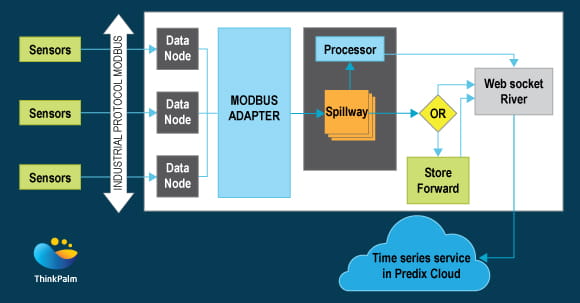
In short, data will be read from various Modbus sensors using Modbus Adapter. It will be sent to the Predix Time series through Spillway and Websocket River. If data needs to stored temporarily, a StoreForward can be configured. Processor, an optional component, can be added for data aggregation or manipulation. We will be able to send the data to Predix time series only when it is authenticated successfully through UAA.
Author Bio
Rajeswari Menon has been working at ThinkPalm as Senior Technical Lead. She is passionate about Java Programming and her hobbies include dancing.